Description of the ODP-505
(Vers la version en Français)
Brief description
Specifications
Photographs! Photos!
Technology details
What would it be able to do today?
The power of this machine is ridiculous the twenty-first century man. But at the time, it was performing machine! They cost about the price of 5 or 6 homes!
Smile a little! What can we do to work with this kind of power?
Biography of this machine. (Story also applies to the OA-1001)
Description of the machine (to write)
End
Brief
description
Specifications
Photos
The place of the ODP-505
Technology details
What would it be able to do today?
Biography of this machine
Description of the machine
Specifications
Photos
The place of the ODP-505
Technology details
What would it be able to do today?
Biography of this machine
Description of the machine
Brief description
The SEREL company (Société d'Etudes et
d'Exploitation Electroniques) studied in the late 50's, 2 computers for
industrial or military use. The first machine, the OA-1001 was a 2 19"
bays of electronics. ODP-505 is an evolution of that first
machine:
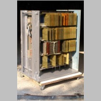
smaller and 3 times faster. It has the size of a low convenient or of a
large washing machine.
This second generation machine, only uses solid state components (germanium transistors and diodes), and ferrite core RAM (with two holes Transfluxor). She is one of 5 or 6 machines survivors of the second generation (with transistors), at the global level.
(See http://pichotjm.free.fr/LiensOrdinosaures.html)
The machine has been built in 1964. (more precisely between 1962 and 1964)
Specifications
Hardware Specifications
Hardware performances, speed:
Clock frequency 1 000 kcy / s (1 MHz).
Memory cycle: 5uS Read, Write 10 uS.
Fetch 57 uS (search for a new instruction)
Addition 45 uS
Subtraction 57 uS
Multiplication 2 mS (18 bits x 18 bits -> 36 bits)
Division 3 mS (36 bit/18 bits -> 18 bits)
Load accu 93 uS (Transfer memory to/from accumulator)
Direct jump 66 uS
Indirect jump 33 uS
I/O access 36 uS (500000 bits/s)
Software Opportunities
Machines from the same period (examples)
- Pure binary machine (18 bits +sign + parity). (No pure BCD, or ASCII operators)
- 1024 words of 20 bits (256 words reserved for microprograms)
- Micro-programmable instructions (germanium diodes). Definable by customers.
- Memory protection against power on or off. (Power supply Sequencer)
- Debugging console with keyboard and display.
- Software and hardware interruptions.
- Input/Output by punched paper (paper), punched cards and tapes.
- Modular construction (plug-in boards).
- Operation in NON-conditioning atmosphere. (15 °C à 30 °C) New for that era!
Reference documents:
- Descriptive summary of the ODP-505
- The machine is derived from the OA-1001, the intimate and detailed operation of the machine is described in references 2: bit level operating description and associated schematics
- Notice on microprogramming uP ODP-505 and code list uProg codes
Hardware performances, speed:
Clock frequency 1 000 kcy / s (1 MHz).
Memory cycle: 5uS Read, Write 10 uS.
Fetch 57 uS (search for a new instruction)
Addition 45 uS
Subtraction 57 uS
Multiplication 2 mS (18 bits x 18 bits -> 36 bits)
Division 3 mS (36 bit/18 bits -> 18 bits)
Load accu 93 uS (Transfer memory to/from accumulator)
Direct jump 66 uS
Indirect jump 33 uS
I/O access 36 uS (500000 bits/s)
Software Opportunities
- Direct and indirect jumps (JMP, JMP,x)
- Call to sub routines: with stack: pointers and context backups . (JSR and RTS) without restriction.
- Return from subrouties (RTS)
- Management of hardware interrupts (pointers and background backups)
- Return from hardware interrupts (RTI)
- 4 levels of interruption priority.
These features make it possible to multiprocessing with scheduler. (Time sharing)
The way was open to the first microprocessor architectures.
You can get an idea of the possibilities of programming in assembler, throwing an eye on a record programming Serel 1001
The way was open to the first microprocessor architectures.
You can get an idea of the possibilities of programming in assembler, throwing an eye on a record programming Serel 1001
Machines from the same period (examples)
- IBM 1401 Machine Management (decimal words) transistors and core memory.
- PDP-1 Process control machine transistors and cores, pure binary, 18-bit, 4 kwords, 200 KHz
- CAB500 from SEA: arithmetic scientific calculator, magnetic cores, magnetic drum.
- ICT 1301
These machines sign the end of an era: The silicon chip was invented in 1958.
After some (a lot of!) improvements, hardware designers, will go thru this new technology and will
create computers with IC, since 1964/1965:
- CDC 6600 from Control Data, machine management.
- PDP-8 from DEC (1st version) process control, and then ...
- IBM 360 machine management.
Photographs! Photos!
- Overview, state restored:

- Details of the empty memory and empty CPU (cards and back planes sides)


- Details of the reinstalled memory:

- Details of the reinstalled CPU


The first machines were scientific calculators (pure BCD numbers or
biquinaires, but with serial CPU), followed by machines for management
(calculation on BCD numbers and strings, with specialized
instructions for BCD, or chains).
The ODP-505 Serel is a binary machine, pure binary working on 19-bit (18 + sign). It may not work on larger numbers than making binary-> BCD transcodings. Work on ASCII strings, can be done only by implementing these binary codes (at the cost of a loss in memory efficiency). It foreshadows really the first microprocessors (which would be a first step in that 4-bit and 8-bit, 16-bit, 32, 64 ...)
The ODP-505 Serel is a binary machine, pure binary working on 19-bit (18 + sign). It may not work on larger numbers than making binary-> BCD transcodings. Work on ASCII strings, can be done only by implementing these binary codes (at the cost of a loss in memory efficiency). It foreshadows really the first microprocessors (which would be a first step in that 4-bit and 8-bit, 16-bit, 32, 64 ...)
Technology details
The
recent invention (ca 1950 ?) of printed
circuit boards (Bakelite, then epoxy), line connectors,
and golden
at the edges of the cards (edge connectors), have created a machine
where modular card plug-in andplug-out were easy (developement
of additional features, fixing and repairing, ...).
The cards will be able to be normalized For example:
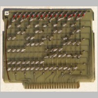
The ODP-505, uses the technology of germanium (diodes and transistors). The elements of logical OR, AND, NOT, OR, AND NON-use diodes followed by transistors (RTL or DTL logic). The 4 -> 16 decoders are by truth table, using a network of diodes (see above).
Previously, electronics will be built by placing components on barettes-media, and we should link the various components through flying wires. (You can see few examples in the photos of this machine) For example here:
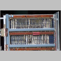 The complex machine building was very difficult,
because during the wiring, many mistakes were done. And
when tested, transistors, very fragile burnt out immediately.
We were trying to save the machine in using fuses everywhere to minimize
the damage ... But it was customary at that time to
say that it was the transistors that protected the fuses! The
use of printed circuits minimized the risk of errors, simplified the
wiring and reduced labor costs.
The complex machine building was very difficult,
because during the wiring, many mistakes were done. And
when tested, transistors, very fragile burnt out immediately.
We were trying to save the machine in using fuses everywhere to minimize
the damage ... But it was customary at that time to
say that it was the transistors that protected the fuses! The
use of printed circuits minimized the risk of errors, simplified the
wiring and reduced labor costs.
The cards (PCBs) can be used single or double-sided. However metallic holes (vias) are not used. (Not yet invented?). The wiring from components to 2 sides calls for a manual welding 2 sides of the card. (A technique known to hackers of our time, who can not afford double-sided circuits)
The oldest PCBs are single-sided and bakelite. The most recent (1964!) are epoxy and double sides. They all have a golden edge connector. There is no back-planes (receiving printed circuit connectors. As in our mother boards of the 2000s). The female connectors are arranged on the rules of metal, and wires (often parallels) are welded to the rear.
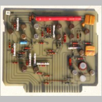
None of the cards has a ground plane! It's quite amazing! It is possible that this is the chassis to serve as a comprehensive reference! (To consider ...)
Components are welded to one side. Many transistors are laid with plastic guide. (with different colors). This allows for very colorful pictures! It's pretty!) Welding is normally done with tin-lead. However there are a few cards using other materials: I suspect welds with Ag, and others with gold! They seems to be manufatures last week! (no oxidation) and appear with a brilliance never seen! They reflections yellow / green very unusual. I never get the effect on photographs.
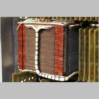
Memory is a ferrite core, classic in those years. It allows random access (hence type RAM) Virtually all machines of that era use memories of this type. We need to understand that the memory 4k words of 20 bits, uses half the volume of the machine. The ODP uses a variant of core memory: Transfluxors. Ferrites with 2 holes.
The pictures you can see core memories photos do not come from this machine. The memory consists of 20 stacks of this style of memory, and is enclosed in a cube of 20 cm side (8") ... That I did not open. It is likely that a program is still in its memory. Future generations may want to read it...
The power supplies (not saved) uses classical analog semi-conductor technology. A voltage sequencer established one after another in a well-defined order. This allowed storing the data in the memory block. [When it is turned on or off of a machine, glitches are generated and create faulty access to memory, destroying data.]
The cards will be able to be normalized For example:
- 4 -> 16 decoder card (demultiplexer / decoder)
- 1 bit register card,
- Analog reading of memory wires of the core memory (1 bit analog) see 11887
- 1 bit address driver (for core wires)
- 1 bit data driver
The ODP-505, uses the technology of germanium (diodes and transistors). The elements of logical OR, AND, NOT, OR, AND NON-use diodes followed by transistors (RTL or DTL logic). The 4 -> 16 decoders are by truth table, using a network of diodes (see above).
Previously, electronics will be built by placing components on barettes-media, and we should link the various components through flying wires. (You can see few examples in the photos of this machine) For example here:
The cards (PCBs) can be used single or double-sided. However metallic holes (vias) are not used. (Not yet invented?). The wiring from components to 2 sides calls for a manual welding 2 sides of the card. (A technique known to hackers of our time, who can not afford double-sided circuits)
The oldest PCBs are single-sided and bakelite. The most recent (1964!) are epoxy and double sides. They all have a golden edge connector. There is no back-planes (receiving printed circuit connectors. As in our mother boards of the 2000s). The female connectors are arranged on the rules of metal, and wires (often parallels) are welded to the rear.
None of the cards has a ground plane! It's quite amazing! It is possible that this is the chassis to serve as a comprehensive reference! (To consider ...)
Components are welded to one side. Many transistors are laid with plastic guide. (with different colors). This allows for very colorful pictures! It's pretty!) Welding is normally done with tin-lead. However there are a few cards using other materials: I suspect welds with Ag, and others with gold! They seems to be manufatures last week! (no oxidation) and appear with a brilliance never seen! They reflections yellow / green very unusual. I never get the effect on photographs.
Memory is a ferrite core, classic in those years. It allows random access (hence type RAM) Virtually all machines of that era use memories of this type. We need to understand that the memory 4k words of 20 bits, uses half the volume of the machine. The ODP uses a variant of core memory: Transfluxors. Ferrites with 2 holes.
The pictures you can see core memories photos do not come from this machine. The memory consists of 20 stacks of this style of memory, and is enclosed in a cube of 20 cm side (8") ... That I did not open. It is likely that a program is still in its memory. Future generations may want to read it...
The power supplies (not saved) uses classical analog semi-conductor technology. A voltage sequencer established one after another in a well-defined order. This allowed storing the data in the memory block. [When it is turned on or off of a machine, glitches are generated and create faulty access to memory, destroying data.]
What would it be able to do today?
The power of this machine is ridiculous the twenty-first century man. But at the time, it was performing machine! They cost about the price of 5 or 6 homes!
Smile a little! What can we do to work with this kind of power?
- Recorder about 1/4 s of music (mono!)
- Records 1 to 2 seconds of telephone conversation. And play back!
- Drive a PC keyboard. (Analysis of the matrix of keys) No USB protocol, anyway!
- Doing the calculations of a scientific calculator. (But no display)
- Read the magnetic strip of a credit card including checking data.
- The control of a washing machine.
- The calculation of the display of a clock. (But without stability)
- Piloting a print head.
- To emulate Windows 1.0
- Read and execute an mp3 file (even mono!)
- A power steering (nuclear?)
- Military and air surveillance.
- Steer a rolling mill.
- Driving nuclear experiments at CEA. (French Atomic Agency)
Biography of this machine. (Story also applies to the OA-1001)
This machine came from the engineering and manufacturing plant of
the Serel Company. (Bd de Mantes à Aubergenville, France 50 miles NW from Paris)
It was built in the early 60's. E-cards bear the date code from 1962 to 1964. It includes a seal of Customs may indicate that it has been exported (perhaps in the USSR for space applications), then it is returned to France. Thereafter, she had to serve for the development of new options or modified designs. Its front is well colored military, and the rear has a blue color recalling the IBM blue!
In 1967 (i was student) or in 1969 (first job), I have no recollection of having seen this machine in operation. In 196x, it has been stored, and then had to be cannibalisée (eaten, just a few) for fixing of other machines. It is probably for these reasons that we find PCBs of similar but with different levels of review.
Towards 1972, we had to find space to install a T1600 mini computer, and the leadership has decided to push all the trash. Having heard it said by my colleagues, that this was the oldest transistor computer designed in France, I am moved and I decided to do everything possible to save this machine. (I also want to tinker with a computer). I am going to see the CEO and have managed to take the machine for a nominal fee.
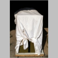
But it was necessary to transport it! A truck, 4 men ... And an unexpected bill! I installed it in a barn (hence the presence of straw at its rediscovery) Life has been such that I have virtually not had an opportunity to nurse it for 35 years ... They remained in this barn without care. In end of December 1999, major storms have destroyed the roof of the barn submitting the machine with a few rains ... of water and tiles! [these two catstrophic storms destroyed about 100 000 000 trees in France, and about the same quantity in the rest of Europe. Hundreds of deads...] Then nothing.
2006 (machine age = 42 years): It is important that the barn is cleared and the machine moves ... Dustbin, museum or rescue?
Some French museums are contacted, and suggests that the machine can be of interest. But nothing concrete and quick decision. However much excitement in the collector family.
Final options: sell the weight of metal, sell abroad or keep?
One can judge the state of the machine, in 2006, row at the back of the barn: http://pichotjm.free.fr/Serel/Photos/Photos.html and see my first tests of restoration in 2006 (to judge of the magnitude of the task): http://pichotjm.free.fr/Serel/Divers/PICT3413.html [bad choice, because the restoration has shown that it was much more complicated and spoiled!]
Some of my children (2) ask me to save the machines and others (2) to clean off! This is my wife (despite the horror of seeing it with us) that advises me to keep it.
We have come to the (ODP-505) transportation. (in 2007, For the transport of the OA-1001, it was much more complicated!). And once at home, helping curiosity, I began a aesthetic restoration (with protection for the next 20 years)
Looking occasionally TV programs on archaeology on Arte channel, I decided to remember as much information as possible. Having a digital camera (I live still with my century! Millenary, as say my sons!), I take a lot of pictures systematically before all my works, and also many notes. If I am wrong, it will always be possible to correct me.
The ODP-505 is now protected in a basement. A measuring system (humidity and temperature) has been installed. But this system has shown that the moisture content amounted to 98%! There were also water seepage during lightning storms or heavy rains. The bloodletting has been cut in the concrete slab; A pump and a dehumidifier (dryer) were also installed. Since then, I can maintain a humidity less than 70% (65% typical) to a temperature of 15 to 16 ° C.
I hope it is ready for a long life!
JM PICHOT, March 3, 2008 (french text)
It was built in the early 60's. E-cards bear the date code from 1962 to 1964. It includes a seal of Customs may indicate that it has been exported (perhaps in the USSR for space applications), then it is returned to France. Thereafter, she had to serve for the development of new options or modified designs. Its front is well colored military, and the rear has a blue color recalling the IBM blue!
In 1967 (i was student) or in 1969 (first job), I have no recollection of having seen this machine in operation. In 196x, it has been stored, and then had to be cannibalisée (eaten, just a few) for fixing of other machines. It is probably for these reasons that we find PCBs of similar but with different levels of review.
Towards 1972, we had to find space to install a T1600 mini computer, and the leadership has decided to push all the trash. Having heard it said by my colleagues, that this was the oldest transistor computer designed in France, I am moved and I decided to do everything possible to save this machine. (I also want to tinker with a computer). I am going to see the CEO and have managed to take the machine for a nominal fee.
But it was necessary to transport it! A truck, 4 men ... And an unexpected bill! I installed it in a barn (hence the presence of straw at its rediscovery) Life has been such that I have virtually not had an opportunity to nurse it for 35 years ... They remained in this barn without care. In end of December 1999, major storms have destroyed the roof of the barn submitting the machine with a few rains ... of water and tiles! [these two catstrophic storms destroyed about 100 000 000 trees in France, and about the same quantity in the rest of Europe. Hundreds of deads...] Then nothing.
2006 (machine age = 42 years): It is important that the barn is cleared and the machine moves ... Dustbin, museum or rescue?
Some French museums are contacted, and suggests that the machine can be of interest. But nothing concrete and quick decision. However much excitement in the collector family.
Final options: sell the weight of metal, sell abroad or keep?
One can judge the state of the machine, in 2006, row at the back of the barn: http://pichotjm.free.fr/Serel/Photos/Photos.html and see my first tests of restoration in 2006 (to judge of the magnitude of the task): http://pichotjm.free.fr/Serel/Divers/PICT3413.html [bad choice, because the restoration has shown that it was much more complicated and spoiled!]
Some of my children (2) ask me to save the machines and others (2) to clean off! This is my wife (despite the horror of seeing it with us) that advises me to keep it.
We have come to the (ODP-505) transportation. (in 2007, For the transport of the OA-1001, it was much more complicated!). And once at home, helping curiosity, I began a aesthetic restoration (with protection for the next 20 years)
Looking occasionally TV programs on archaeology on Arte channel, I decided to remember as much information as possible. Having a digital camera (I live still with my century! Millenary, as say my sons!), I take a lot of pictures systematically before all my works, and also many notes. If I am wrong, it will always be possible to correct me.
The ODP-505 is now protected in a basement. A measuring system (humidity and temperature) has been installed. But this system has shown that the moisture content amounted to 98%! There were also water seepage during lightning storms or heavy rains. The bloodletting has been cut in the concrete slab; A pump and a dehumidifier (dryer) were also installed. Since then, I can maintain a humidity less than 70% (65% typical) to a temperature of 15 to 16 ° C.
I hope it is ready for a long life!
JM PICHOT, March 3, 2008 (french text)
Description of the machine (to write)
Overview
The back side (back planes)
Implantation of memory (with links to boards) here: .../Serel/ODP505/Disposition.html
Implantation of CPU (with links to boards) here: .../Serel/ODP505/DispositionCPU.html
Description cards (to do)
Method to reconstruct the schematics (to write, screen shots have been saved)
Take a schematic editor and a PCBs editor (manual wiring).
1- Report simultaneously components and 'wires'. (Thinking about setting up components)
2- Playing with netlists and the DRC (design rule check) to eliminate errors.
3- Once the complete report ok, change the pattern to be read by an electronics engineer.
I tried this method for 2 types of cards: one is the 13-bit ADC converter of OA-1001, and the other concerns a buffer board. It's very cumbersome as a method: nearly one week per card!
The back side (back planes)
Implantation of memory (with links to boards) here: .../Serel/ODP505/Disposition.html
Implantation of CPU (with links to boards) here: .../Serel/ODP505/DispositionCPU.html
Description cards (to do)
For each card:
- Photos components side
- Photos welding side
- Reconstituted schematics
- Functioning
Method to reconstruct the schematics (to write, screen shots have been saved)
Take a schematic editor and a PCBs editor (manual wiring).
1- Report simultaneously components and 'wires'. (Thinking about setting up components)
2- Playing with netlists and the DRC (design rule check) to eliminate errors.
3- Once the complete report ok, change the pattern to be read by an electronics engineer.
I tried this method for 2 types of cards: one is the 13-bit ADC converter of OA-1001, and the other concerns a buffer board. It's very cumbersome as a method: nearly one week per card!
End
Copyrights JM Pichot
2008-03-10 first edition/translation
(The CPU has been published before)

Since 10mar2008
site root
2008-03-10 first edition/translation
(The CPU has been published before)
Since 10mar2008
site root